|
MCL-Designer V4's Workflow |
  
|
MCL-Designer V4's Workflow
|
MCL-Designer V4's Workflow |
|
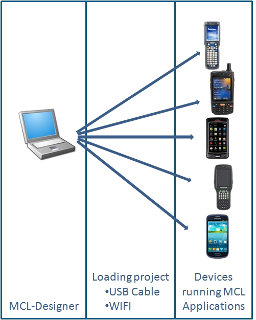
MCL-Designer V4's Basic Architecture
The illustration below displays a basic workflow when using MCL-Designer V4:
The project is created in a workstation and, after it is finished, it is loaded, via USB cable or WiFi, to the device. |
The Development Workflow of an MCL-Designer V4 Project
The illustration below displays a typical development workflow within MCL-Designer V4, starting with new project creation, and ending with the sending of a completed project (that is to say, an application) to a device.

Step-by-Step
1. Create a new project. See Creating a New Project.
2. Edit the initial program ("Main program") which is automatically added after creating a new project.
Create all the necessary program routines and procedures in the Main program. See How to Work with Programs.
3. Edit the initial screen which is automatically generated after creating a new project.
4. Add controls to the screen (items such as text, shapes, menu buttons, etc.) and edit their style for customization. See How to Work with Screens.
5. Add processes to the screens and the controls within (processes contain the logic of the application). See How to Work with Processes.
6. Create any additional programs that are required for the application (for example, an inventory program, an audit program, etc.) and furnish them with screens, program routines, procedures and processes. (repeat steps 4 to 5). See How to Work with Programs.
7. Use MCL-Designer V4.'s "Verifier" to make sure the project does not contain any inconsistencies or errors. See Detailing the Icon Shortcut Bar.
8. Test the applications on your computer, with the help of the simulator contained in MCL-Designer V4. These simulation and debugging steps are useful for highlighting logic flow and code flaws. See Simulating a Project.
9. Finally, once the project is thoroughly tested, it can be moved to the production environment by using the "Load to Device" option (located in the "Menu Bar" area > "Project") or the ![]() icon. The project is now ready for production use. See Loading an Application/Project to a Device.
icon. The project is now ready for production use. See Loading an Application/Project to a Device.
Example of an Application Workflow
Below is an example of the workflow of a simple data collection application:
The operator enters the number of the reference document ("Header" screen) and, then, reads an item's barcode ("Item" screen). As an addition, the operator can view the scanned items, delete all entries or print the file ("List" screen).
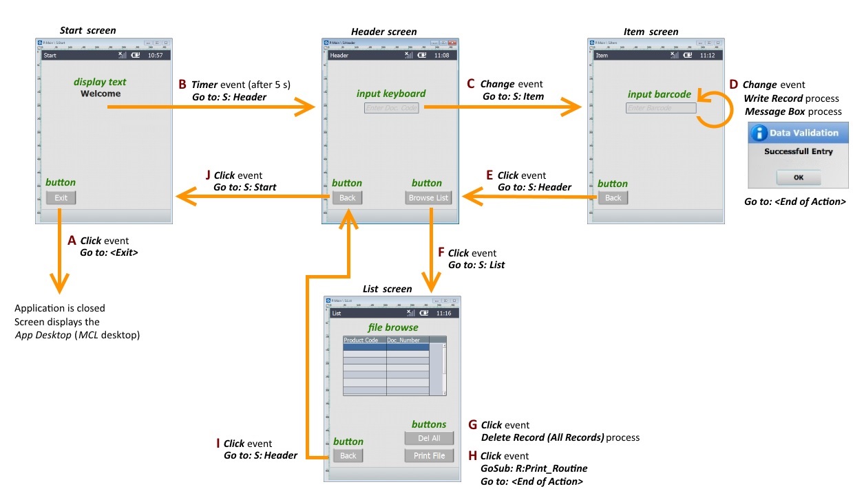
In this example, most of the workflow is managed via Button controls. Each Button control contains the default “Click” action (event performed by the operator that triggers processes) to which a "Go to" process with a specified destination was added. As a result, whenever the operator clicks a specific Button in the device’s screen, he is redirected according to the destination you have selected within that "Go to" process (ex: I - In the "List" screen, if the operator clicks the Button “Back”, he will proceed to the "Header" screen).
The default action associated to an Input Keyboard or an Input Barcode control is a “Change” action (ex: "Header" and "Item" screens). In this case, the process(es) you add to the action are triggered when the operator enters data and presses <ENTER> in the device’s keyboard, or simply scans a Barcode.
The purpose of the "Header" screen is to collect the document number and redirect the operator to the "Item" screen. So, a process was added(C) to the Input Keyboard control:
•"Go to S: Item"
The purpose of the "Item" screen is to save the entered data into a file and view a data input confirmation window. Therefore, 3 processes were added to the Input Barcode control (D):
•"Write Record" <name of the file where the data is being written>
•Message Box
•"Go to <End of Action>" to ensure the end of the file writing and allow the next scan
This data collection application also allows the operator to check the data being entered. Once the operator is redirected to the "List" screen, with the help of the “Browse List” Button, you can not only view the entered data (in the File Browse control) but you can also delete that data. In this case, the Button “Dell All” does not redirect the program’s workflow to another screen (there is no "Go to" process added to the “Click” action) but performs a delete operation (G).
If required, the operator can print the file.
The default “Click” action of the “Print File” Button on the "List" (H) screen includes a specific "Go to" process ("GoSub") that calls for a routine (routine = a set of processes representing specific or recurrent tasks) designed to trigger the printing of the file displayed in the File Browse control. The routine must finish its processing with a "Go to <Exit>" and the “Click” action of the “Print File” Button should include a "Go to <End of Action>" process which is necessary to conclude the action.
As a result, when the operator clicks the “Print File” Button, the routine is called and the file is printed.